Gyration Gyromouse battery replacement with normal cells, been working fine for a year. Can use normal charger or standard Gyration charger without overheating or damage. Only slight modifications needed to pack, pretty self explanatory. Still in use. (2007/2008-current)
| From Gyro Mouse battery pack replacement |
Below is HTML from an old phpWiki I had, some useful info, some useless. Just archiving so i can shut that old thing down. It's a risk to keep running. Cleaned up some html and made links anchors, tried to put the smaller pages all on one page. Will make the two larger video wall and ledsign posts separate.
October 7, 2004
LIST -al
150 Opening ASCII mode data connection for '/bin/ls'.
226 Transfer complete.
OpenEEG - an open source project building hardware and writing software for the measurement and interpretation of brain wave activity.
VideoWalls - hacked up televisions made into large scale projectors.
LedSign - an old scrolling sign repurposed.
Xbox - getting eeprom contents from a dead motherboard via I2C interface.
Flex - flex pager modification for intercepting POCSAG/FLEX radio traffic.
QUIT
221 Goodbye.
Ideas:
RGBAmbilight
OpenEEG (August 30, 2004 7:39 pm)
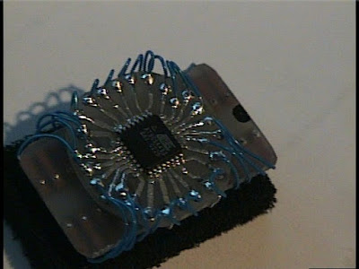 |
| From OpenEEG |
(2009 edit: There never was a writeup on this, just build pics. See the OpenEEG project for more details. This was my admittedly crude build in 2004. My ch2 was a little flakey and the DRL never seemed to work right. I guess I gave up trying to build my super sensory overload biofeedback machine (lol) when I couldn't get reliable results from the equipment. I learned a lot building this, the first 2 sided diy etched board I'd made. Some comments to the dev's helped invoke design changes that it's assembly easier for DIYrs, mostly double sided thru hole issues, where a diy'r would not have proper via's.)
Gallery
RGB Ambilight (March 13, 2006 4:37 pm)
Ambient lighting system made from RGB LED array sticks + XBox.
The sticks could be serial or USB controlled and tied into XBMC via a hacked serial port or xbox prerprial that has output. (even vibration output could be modulated into a serial stream of data)
Code would find the average screen color and intensity, and match the RGB LED's to those values. This should tie in easily to XBMC's pixel shader rendering engine.
The sticks would be positioned in a way so as not to interfere with the projected media, yet supply a ambient gradient of light surrounding the screen making it appear larger and immersing the viewer. Alternatively, they could be positioned behind the viewer to color the surroundings.
This is in essence a DIY Phillips Ambilight system. (2009 edit: hello! welcome to the future!)
Decoding pager messages (August 24, 2004 6:09 pm)
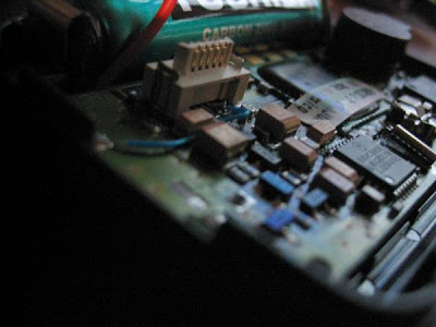 |
| From flex |
I wanted to receive FLEX pager transmissions in my area, but my crappy scanner doesn't do the 900mhz range(its old). So I figured that a pager has to be a radio anyways, and I took apart a broken flex pager and found the radio output. From there it went to the mic input on the decoding computer for the software to deal with. Hey, it worked.. Gallery
XBox I2C EEPROM dump (August 22, 2004)
So I was given a fried XBox in the hopes it could be resurrected. It would turn on but do the Christmas light 'frag'. In the whole process of playing with it I did execute a nifty way of reading the eeprom. The information is here For programming IC-Prog is used. It used 2 resistors and 2 transistors hooked to the serial port. You can retrieve your XBox serial number, HD Password, and valid Live serial, etc from this method.
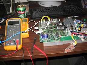 |
| From xbox1 dump i2c |
EEPROM Programming
Setting for the programmer in IC-Prog
Under menu Settings/Hardware:
Programmer = JDM Hardware
Communication (check boxes for the following)
Inverted Data out
Inverted Clock
For programming serial EEPROM on the xbox
Under menu Settings/Device -> Select I2C EEPROM / 24C02
Under menu Settings/Options -> Select Tab I2C -> Hardware Address = 84
Command/Read All : Read EEPROM into buffer
Command/Program All : Write buffer into EEPROM
Gallery
LEDSign (September 15, 2004)
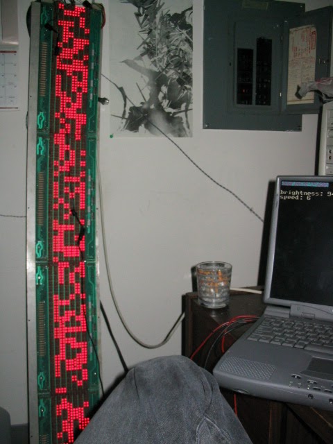
An early test of the software that randomized the display.
I've had this sign since I was about 17 years old and have been carrying it around with me everywhere I've moved. It's a 7x96 pixel sign display made by Colorado Data Display. I imagine it's from the eighties. I never had the keyboard for it so programming was a pain. I figured out the keyboard connector was nothing but a key matrix input(10X, by 10Y and some extras like reset button) so I had a piece of cardboard with a grid on it filled with letters that had been figured from trial and error. The wires were old cut up phone cord taped to the side of the cardboard, with one wire between each grid line. When you wanted to press a button, you hooked the alligator clip to a row and touched the respective column. Yes, it really sucked. The hardware could do regular sign effects, drop, scroll, etc and was pretty dull. The unit had an 8085 CPU and eprom for code storage. The dream I always had was to somehow feed my own data into it. It had crazy connectors on the board, some kind of unpopulated fiber optic input, a direct bus connection, and unpopulated serial input. In order to populate the serial portion of the motherboard, I would have had to acquire a 9600 baud UART and other mystery chips. On top of that, I didn't even know if the code to accept serial input was in the ROM, or what protocol it used etc. With tons of unknowns, more and more I just wanted to cut the whole logic board out of the unit. Several years past with it collecting dust in different closets every few months. While ordering parts for some other crap I was building at the time, I ordered 70 something micro buttons and etched a keyboard for the unit. Now I had a keyboard for it, I could make stupid messages scroll by in my house with ease. I'm sure I'll be desoldering those buttons for more useful shit in the near future. Finally I came to the realization that I had to reverse engineer the whole drive circuitry if it was ever to be any more than all the other junk I collect. Looking back this really was not too difficult to do. I sat down with some graph paper and my Fluke, and started drawing out the traces. The two pictures below are the result. The led boards(4) are detachable and contain 7x24 pixels each. When connected all together, they get input from one end of the chain where the drive control is located. After the schematics were complete, I proceeded to cut all traces joining the drive circuits from the logic/cpu section of the board, while keeping the power traces intact. I soldered on a DB25 printer cable for the PC interface and hot glued it to the board so it couldnt be ripped off.

Led board with control board connections.
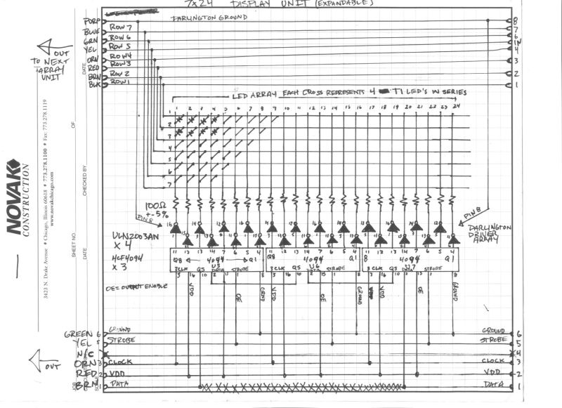
Schematic of one LED sign segment.
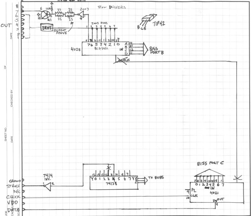
Tidbits of the power transistors that control the rows
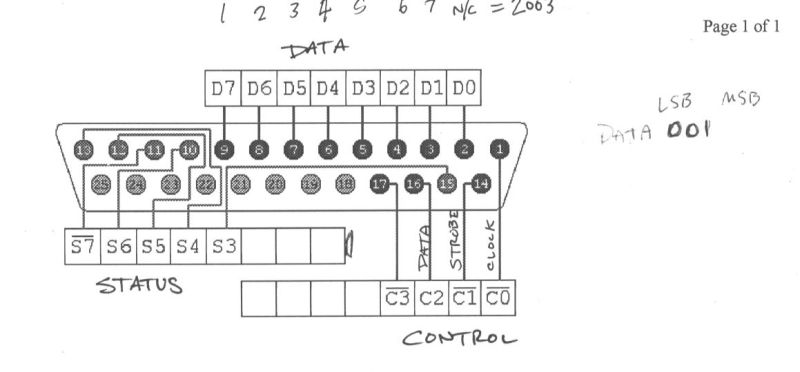
A cheat sheet to show me where I put the wires while programming.
Alright, so now it was hooked to the computer but it's not like you can start putting text on it just like that. Since the sign has no brains anymore, it also has no character set, interface, protocol or anything. It's just some dumb lights attached to your printer port. I hooked the columns to the 'control' and the row inputs to the 'data' portions of the lpt interface. It all works like a grid, if you activate a row, it connects that row to a positive source of current. All the lights in that row now have their anode connected to a proper supply, but they dont have a cathode yet so no current actually flows thru them, and they don't light up. In comes these little chips called 4094 shift registers. Theres 3 of them on each sign module(out of 4) and they each have 8 outputs each. Without getting too much into detail, you pump ones and zeros into a pin, along with a clock signal, and the chip pushes the data over to the next output.

In the animation above, we can see how the four-bit binary number 1001 is shifted to the Q outputs of the register.
When the chips are chained together like in the circuit, the data flows along each chip until you've filled up the whole sign with your desired pattern. When youre ready to show your lights, you trigger the OE(output enable) pin and it causes the 8 outputs on each chip to switch on. From there the current goes into a darlington driver, which simply allows a greater amount of current to be switched on and off than the 4094's can handle. If the drivers weren't there, the magic smoke would definitely escape from the 4094's. The darlingtons give the desired LED's their cathode connection to the ground plane and they turn on. So now we have some illumination, but we can only turn on individual pixels in a column and row, but all the rows are the same like in this picture.
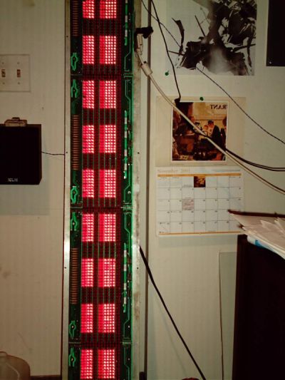
This is because the sign works as a matrix, and has to be scanned very quickly to trick our eyes into thinking more than one row is on at a time. The process is this: Pump 96 bits of ones and zeros into the 4094's(one bit for each column, one is on, zero is off), turn on the OE(strobe in our case) pin so the cathodes get turned on, turn on the row 1 pin so the anodes are on and pause for some milliseconds, and finally turn off the row 1 pin and 4094 OE pin. Repeat replacing the row pin with the remaining rows and you have a working sign. Brightness is controlled by adjusting the pause time in each row. I wrote some qbasic code to do all this, and designed a character set in Photoshop. The character set was then transcribed by hand to an array in the software. The software is pretty intensive and requires a dedicated computer to run it, because the scanning has do be done at a very fast rate to trick the eyes.(2009 edit: and because I sucked at programming and didn't know about microcontrollers!) Eventually serial input was added along with a console for commands. Later this was all scrapped and emulation was coded in instead, so the sign could act as a normal serial LCD display(I chose a Crystal Fontz to emulate) like the ones people have in their cases for temps and such. This enabled me to use the sign with pre-existing software and plugins. Currently I use it to pull RSS feeds from the BBC World news and scroll them across the sign.
The sign displaying some characters for the first time.
The date and time.
The sign displaying the news.
Some time was spent writing software to run it on my main machine in VB6. This was before I realized it really needed its own dedicated proccesor(just like it had before I butchered it). However some nifty effects were produced(at 100% cpu usage on a P4 2.6Ghz, because of the NT LPT port?). Sound card sampling and FFT analysis was dumped into an array and pushed out to the sign. Here are 2 videos(2009 edit: only uploaded relevant one) showing it in action(Boards of Canada as input) before the project was moved to the dedicated machine.
The sign displaying messed up FFT frequency data.
i was just thinking about POCSAG the other day, been listening to old Off the Hook episodes at work. i really miss that shit, the analog days were the best.
ReplyDelete