Friday, November 13, 2009

Arduino Universal Remote - Code Followup

Original Post
Here is the service, source code and installer included: download
Edit: This was updated 1/22/10, fixes: config file was not being read properly, added shortcuts to configuration folder and start/stop commands for service. Remember to read the readme and put your audio device guid's in the config if you want the audio output polling feature to work.

A windows power management event triggers a byte to be sent to the microcontroller, which then sends out an IR code. Optionally, the default sound device is polled via DirectX and any changes detected cause an IR code to be sent to change the input on the amp.

Here is the code for the microcontroller, it simply gets a byte from the serial port and decides what to do based on its value. It sends back a linefeed as an ack. The button is just a simple on/off, totally optional.

/*
* electrosthetics IRremotePowerSave: power saving project - microcontroller side
* info : http://electrosthetics.blogspot.com/2009/11/arduino-universal-remote-and-more.html
* IRremote lib Copyright 2009 Ken Shirriff http://arcfn.com
*
*/

#include

IRsend irsend;
int on = 0;
int BUTTON_PIN = 12;
int STATUS_PIN = 13;
int inByte = 0;

void setup()
{
Serial.begin(9600);
pinMode(BUTTON_PIN, INPUT);
pinMode(STATUS_PIN, OUTPUT);
}

void loop() {
if (Serial.available() > 0) {

// get incoming byte:
inByte = Serial.read();
switch (inByte) {
case 0x01:
irsend.sendNEC(0x817E817E, 32); // send on
on = true;
break;
case 0x02:
irsend.sendNEC(0x817E01FE, 32); // send off
on = false;
break;
case 0x10:
irsend.sendNEC(0xA15E1EE1, 32); // send MultiChan
break;
case 0x11:
irsend.sendNEC(0xA15E7C83, 32); // send DVD
break;
}
Serial.write("\n");
digitalWrite(STATUS_PIN, HIGH);
delay(500);
digitalWrite(STATUS_PIN, LOW);

} else {
if (digitalRead(BUTTON_PIN)) {
if (on) {
irsend.sendNEC(0x817E01FE, 32); // send off
on = false;
} else {
irsend.sendNEC(0x817E817E, 32); // send on
on = true;
}
digitalWrite(STATUS_PIN, HIGH);
delay(1000);
digitalWrite(STATUS_PIN, LOW);
}
}
}

Friday, November 6, 2009

An Arduino universal remote and more

Edit: Code here

So I have a large 7.1 surround system hooked to my computer for games and watching movies (when the 720p projector is on). This is a large external receiver, a Yamaha RXV663. It uses enough current to keep it warm even if sound isn't coming out of it. Thing is, I have been putting my computer to sleep for a few years now, but I always forget to turn the receiver off. Being lazy/forgetful like that, I ordered an extra boarduino a while ago to solve the problem. Now I'm finally putting it to use.

I scavenged a couple parts.. the 3 pin IR receiver from an old Audigy LiveDrive (those 5 1/4 drive bay things with jacks and such.. never used the crappy remote anyways) and an old IR remote which I broke in half and soldered a header on to. The IR led's seem to draw a lot of current so I put a 1000uf cap on the power rails. (they are pulsed via switching transistor)

The real workhorse here is this guys IR library:

Arc Language Blog: An Arduino universal remote: record and playback IR signals

I only had to modify an include file to make the existing NEC remote routine interpret and send Yamaha codes. I'm not sure if I did it all right, but it wasn't really important to me as long as it could send the codes I needed.
I only had to modify these values:
// pulse parameters in usec
#define NEC_HDR_MARK 8900
#define NEC_HDR_SPACE 4600
#define NEC_BIT_MARK 600
#define NEC_ONE_SPACE 600
#define NEC_ZERO_SPACE 1700
#define NEC_RPT_SPACE 2250

and simply send the code like this:
irsend.sendNEC(0x817E01FE, 32); // send turn off
or
irsend.sendNEC(0x817E817E, 32); // send turn on

You can see that those codes match these from the LIRC site, minus whatever prefix 817E is (could be a part of the header?) Anyways, it works great.

Now I'm off to write the other part of it, a C# app that will detect a PowerModeChanged event (documented here) and send an OFF pulse when the machine is entering standby, ON when it is waking up. I want it to leave it alone when the computer is rebooting so it doesn't needlessly cycle the relays in the amp.. it will send some info over the arduino's serial port via USB. (I thought I could get away with using DTR or something, and no app on the computer but no dice. Alternatively I could use something like the power LED on the case to signal the arduino, but I didn't want to mess with small gauge wires sticking out and getting cut on things) So I'm pretty committed to an always running c# app that will keep the arduino informed of the computers status.

With this system I can also send the other codes that have been documented on the LIRC site too, an example usage:
When I watch movies with the projector, I switch the input on the amp to be a coaxial SPDIF input and set windows to use the digital out, so that I get unmolested bitaccurate audio from whatever I'm watching.
However when I'm playing a game, I need to use the analog 7.1 sound card outputs and the multichan input on the amp.

With this power management monitoring app, maybe it could get the current default audio device and switch the amp input based on that.. all automatic! Next it will be dispensing beer into my mouth while watching movies.

Kudos to Ken for his arduino IR library!

Code for this is in the followup post here. It works great!

I am going to buy one of those tiny miniusb arduino's for this, and put it in a little box with a jack for an IR blaster.

Here is a bad picture of the prototype

Monday, May 18, 2009

AmbX Peripheral Fake Out - Part II

Ok, here is the final, 100% correct pinout. Now start connecting weird things to your AmbX without fear of explosion or death!

Notes:
  • These were pinned and drawn from actual Fan and Rumbler accessories.
  • The left diagram is the Rumbler, the right diagram is either of the fan jacks. The polarity on those motors is not very important but provided nonetheless. (there is a small red dot on the motor)
  • There is no resistor for the jumper. I used one when I was messing about because its safer than just shorting unknown things out. But now we know there isn't one for sure.
  • Too bad both jacks make use of pins that aren't on S-video cables. Otherwise I'd just knock out the plastic insert and use one of those. You could use it on the Fan one if you provided your own external power supply I suppose.
  • The Rumbler (can we call it something else?) has 2 zones, Right and Left. But on the one I took apart, you'll notice someone put glue between their joint, defeating the whole purpose of the rubber standoffs that isolate the two zones from themselves and the base. Besides that, its effectiveness is questionable.. a friend said "Who plays FPS's with the keyboard (alone) anymore?".. Good point, unless you are playing DOOM or something where both hands are on the keyboard, the right side rumbler is mostly useless. Exxxxtreme numpad plugin for Excel coming soon! Feel those numbers and formulas come to life! (I admit, I love the numpad and can't live without it. I'd sacrifice the speakers on my MBP to have a numpad.)
From AmbX Disassembly

Click for more pics

Sunday, May 17, 2009

AmbX Peripheral Fake Out

Edit: If you just want the pinout, skip ahead to part 2.

Had a few minutes tonight to use a classic technique of sticking safety pins (not safe!) into those rear jacks and seeing if anyone's home and how they respond to threats. Found an interesting 3.3v which I immediately thought was a floating input sense. Turns out when you ground that (pull down via a 1k resistor), you've got some extra fan's and a rumble pad! Here's a rough diagram from what I could see with an old Simpson 260 meter (easier to see PWM on old analog meter, although you can't read the pulse width.. scope is broke at the moment) I have not verified these by connecting actual motors yet, just the meter. I would wager the diagram is mostly correct, especially the fans.. they are very simple. The 'Direct Control' software will detect your fans and rumble in realtime when you put the resistor in the back. (I just stuck mine in the back socket pins, maxin relaxin.) If you can't find that app, look under Philips Accessories.. it doesn't live with the rest of the suite.


Erm, that 'OUT' is electron flow, not conventional. I could have wrote PWM return but whatevs. The point is: the VCC is constant, the PWM signal is ground. :)

Sunday, May 3, 2009

Old Projects Archive

Looking back, I really miss all the time I had back then to do these things. (no serious job, just getting by helping people out or people helping me out, using free time to experiment) Now it's very hard to dedicate any time to anything for any period of time. I can say the fault is not having more responsibility, not that I have any place to speak about such things.. been avoiding it all my life, the only one I have is a house loan now. But avoiding responsibility does not immediately lead to not being productive or successful, it just means not being tied down. (imo) But I think it is the 40 hour work week that really did me in, time just slides by now, I don't know whats going on half the time. Being young is precious, you have a strong moral compass, impatience, will to act, fearlessness. Hold on to that, don't let it go. Anyways here are a few that I actually documented, I wasn't big on planning or reflection, only worthless bits of paper with hex codes or little circuit schematics remained.


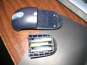
Gyration Gyromouse battery replacement with normal cells, been working fine for a year. Can use normal charger or standard Gyration charger without overheating or damage. Only slight modifications needed to pack, pretty self explanatory. Still in use. (2007/2008-current)
From Gyro Mouse battery pack replacement


Below is HTML from an old phpWiki I had, some useful info, some useless. Just archiving so i can shut that old thing down. It's a risk to keep running. Cleaned up some html and made links anchors, tried to put the smaller pages all on one page. Will make the two larger video wall and ledsign posts separate.

October 7, 2004
LIST -al
150 Opening ASCII mode data connection for '/bin/ls'.
226 Transfer complete.
OpenEEG - an open source project building hardware and writing software for the measurement and interpretation of brain wave activity.
VideoWalls - hacked up televisions made into large scale projectors.
LedSign - an old scrolling sign repurposed.
Xbox - getting eeprom contents from a dead motherboard via I2C interface.
Flex - flex pager modification for intercepting POCSAG/FLEX radio traffic.
QUIT
221 Goodbye.
Ideas:
RGBAmbilight


OpenEEG (August 30, 2004 7:39 pm)
From OpenEEG

(2009 edit: There never was a writeup on this, just build pics. See the OpenEEG project for more details. This was my admittedly crude build in 2004. My ch2 was a little flakey and the DRL never seemed to work right. I guess I gave up trying to build my super sensory overload biofeedback machine (lol) when I couldn't get reliable results from the equipment. I learned a lot building this, the first 2 sided diy etched board I'd made. Some comments to the dev's helped invoke design changes that it's assembly easier for DIYrs, mostly double sided thru hole issues, where a diy'r would not have proper via's.)
Gallery


RGB Ambilight (March 13, 2006 4:37 pm)
Ambient lighting system made from RGB LED array sticks + XBox.
The sticks could be serial or USB controlled and tied into XBMC via a hacked serial port or xbox prerprial that has output. (even vibration output could be modulated into a serial stream of data)
Code would find the average screen color and intensity, and match the RGB LED's to those values. This should tie in easily to XBMC's pixel shader rendering engine.
The sticks would be positioned in a way so as not to interfere with the projected media, yet supply a ambient gradient of light surrounding the screen making it appear larger and immersing the viewer. Alternatively, they could be positioned behind the viewer to color the surroundings.
This is in essence a DIY Phillips Ambilight system. (2009 edit: hello! welcome to the future!)


Decoding pager messages (August 24, 2004 6:09 pm)
From flex

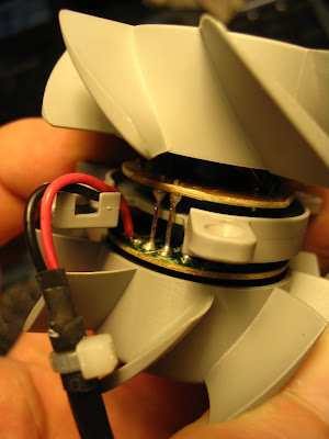
I wanted to receive FLEX pager transmissions in my area, but my crappy scanner doesn't do the 900mhz range(its old). So I figured that a pager has to be a radio anyways, and I took apart a broken flex pager and found the radio output. From there it went to the mic input on the decoding computer for the software to deal with. Hey, it worked.. Gallery


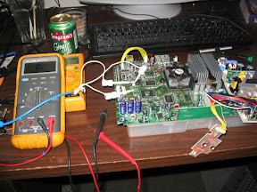
XBox I2C EEPROM dump (August 22, 2004)
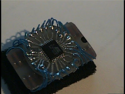
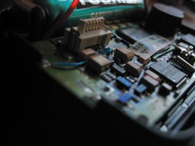
So I was given a fried XBox in the hopes it could be resurrected. It would turn on but do the Christmas light 'frag'. In the whole process of playing with it I did execute a nifty way of reading the eeprom. The information is here For programming IC-Prog is used. It used 2 resistors and 2 transistors hooked to the serial port. You can retrieve your XBox serial number, HD Password, and valid Live serial, etc from this method.
From xbox1 dump i2c

EEPROM Programming
Setting for the programmer in IC-Prog
Under menu Settings/Hardware:
Programmer = JDM Hardware
Communication (check boxes for the following)
Inverted Data out
Inverted Clock

For programming serial EEPROM on the xbox

Under menu Settings/Device -> Select I2C EEPROM / 24C02
Under menu Settings/Options -> Select Tab I2C -> Hardware Address = 84
Command/Read All : Read EEPROM into buffer
Command/Program All : Write buffer into EEPROM

Gallery


LEDSign (September 15, 2004)

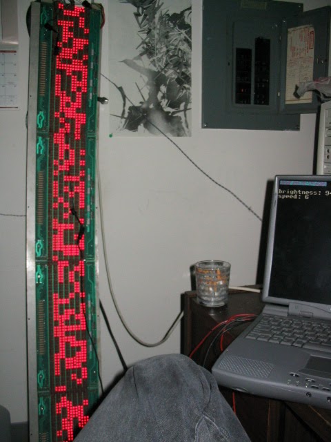
An early test of the software that randomized the display.
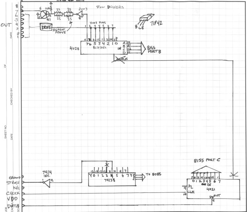
I've had this sign since I was about 17 years old and have been carrying it around with me everywhere I've moved. It's a 7x96 pixel sign display made by Colorado Data Display. I imagine it's from the eighties. I never had the keyboard for it so programming was a pain. I figured out the keyboard connector was nothing but a key matrix input(10X, by 10Y and some extras like reset button) so I had a piece of cardboard with a grid on it filled with letters that had been figured from trial and error. The wires were old cut up phone cord taped to the side of the cardboard, with one wire between each grid line. When you wanted to press a button, you hooked the alligator clip to a row and touched the respective column. Yes, it really sucked. The hardware could do regular sign effects, drop, scroll, etc and was pretty dull. The unit had an 8085 CPU and eprom for code storage. The dream I always had was to somehow feed my own data into it. It had crazy connectors on the board, some kind of unpopulated fiber optic input, a direct bus connection, and unpopulated serial input. In order to populate the serial portion of the motherboard, I would have had to acquire a 9600 baud UART and other mystery chips. On top of that, I didn't even know if the code to accept serial input was in the ROM, or what protocol it used etc. With tons of unknowns, more and more I just wanted to cut the whole logic board out of the unit. Several years past with it collecting dust in different closets every few months. While ordering parts for some other crap I was building at the time, I ordered 70 something micro buttons and etched a keyboard for the unit. Now I had a keyboard for it, I could make stupid messages scroll by in my house with ease. I'm sure I'll be desoldering those buttons for more useful shit in the near future. Finally I came to the realization that I had to reverse engineer the whole drive circuitry if it was ever to be any more than all the other junk I collect. Looking back this really was not too difficult to do. I sat down with some graph paper and my Fluke, and started drawing out the traces. The two pictures below are the result. The led boards(4) are detachable and contain 7x24 pixels each. When connected all together, they get input from one end of the chain where the drive control is located. After the schematics were complete, I proceeded to cut all traces joining the drive circuits from the logic/cpu section of the board, while keeping the power traces intact. I soldered on a DB25 printer cable for the PC interface and hot glued it to the board so it couldnt be ripped off.

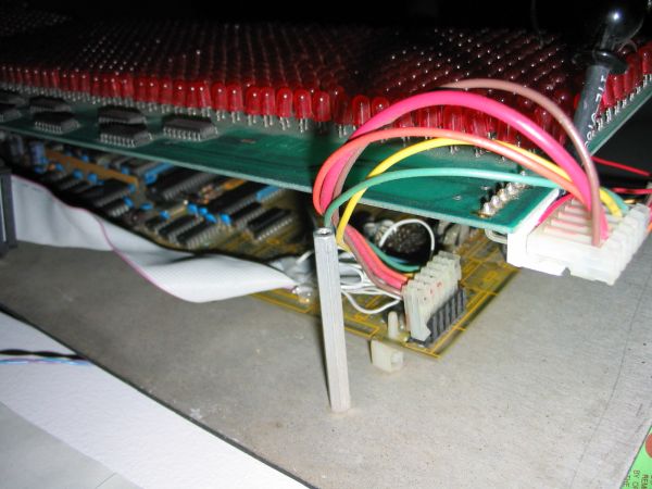
Led board with control board connections.

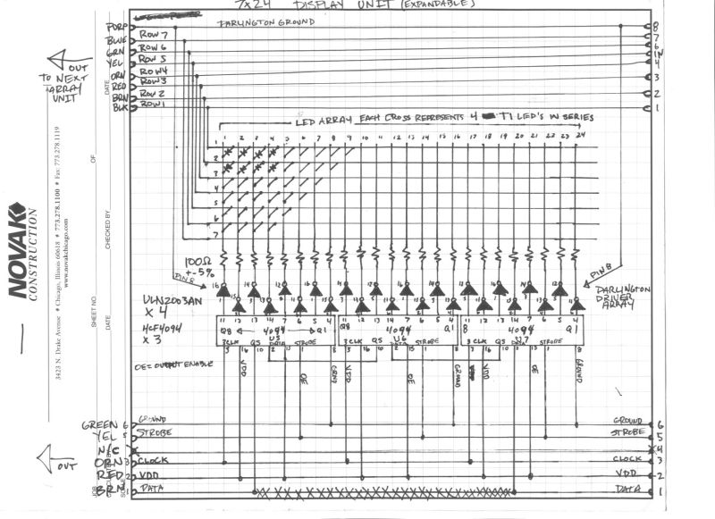
Schematic of one LED sign segment.


Tidbits of the power transistors that control the rows


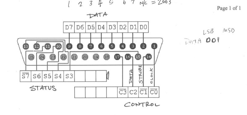
A cheat sheet to show me where I put the wires while programming.

Alright, so now it was hooked to the computer but it's not like you can start putting text on it just like that. Since the sign has no brains anymore, it also has no character set, interface, protocol or anything. It's just some dumb lights attached to your printer port. I hooked the columns to the 'control' and the row inputs to the 'data' portions of the lpt interface. It all works like a grid, if you activate a row, it connects that row to a positive source of current. All the lights in that row now have their anode connected to a proper supply, but they dont have a cathode yet so no current actually flows thru them, and they don't light up. In comes these little chips called 4094 shift registers. Theres 3 of them on each sign module(out of 4) and they each have 8 outputs each. Without getting too much into detail, you pump ones and zeros into a pin, along with a clock signal, and the chip pushes the data over to the next output.


In the animation above, we can see how the four-bit binary number 1001 is shifted to the Q outputs of the register.

When the chips are chained together like in the circuit, the data flows along each chip until you've filled up the whole sign with your desired pattern. When youre ready to show your lights, you trigger the OE(output enable) pin and it causes the 8 outputs on each chip to switch on. From there the current goes into a darlington driver, which simply allows a greater amount of current to be switched on and off than the 4094's can handle. If the drivers weren't there, the magic smoke would definitely escape from the 4094's. The darlingtons give the desired LED's their cathode connection to the ground plane and they turn on. So now we have some illumination, but we can only turn on individual pixels in a column and row, but all the rows are the same like in this picture.

This is because the sign works as a matrix, and has to be scanned very quickly to trick our eyes into thinking more than one row is on at a time. The process is this: Pump 96 bits of ones and zeros into the 4094's(one bit for each column, one is on, zero is off), turn on the OE(strobe in our case) pin so the cathodes get turned on, turn on the row 1 pin so the anodes are on and pause for some milliseconds, and finally turn off the row 1 pin and 4094 OE pin. Repeat replacing the row pin with the remaining rows and you have a working sign. Brightness is controlled by adjusting the pause time in each row. I wrote some qbasic code to do all this, and designed a character set in Photoshop. The character set was then transcribed by hand to an array in the software. The software is pretty intensive and requires a dedicated computer to run it, because the scanning has do be done at a very fast rate to trick the eyes.(2009 edit: and because I sucked at programming and didn't know about microcontrollers!) Eventually serial input was added along with a console for commands. Later this was all scrapped and emulation was coded in instead, so the sign could act as a normal serial LCD display(I chose a Crystal Fontz to emulate) like the ones people have in their cases for temps and such. This enabled me to use the sign with pre-existing software and plugins. Currently I use it to pull RSS feeds from the BBC World news and scroll them across the sign.


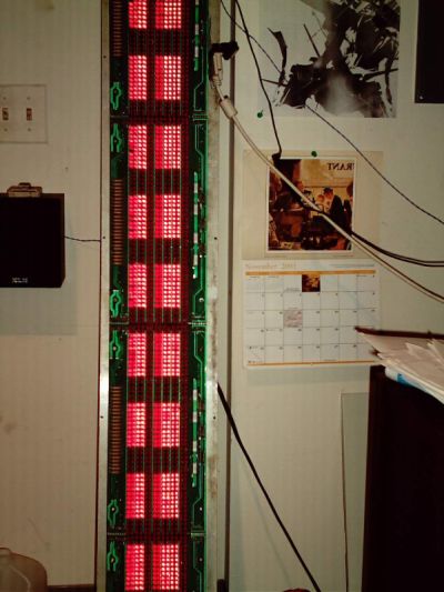
The sign displaying some characters for the first time.

The date and time.

The sign displaying the news.

Some time was spent writing software to run it on my main machine in VB6. This was before I realized it really needed its own dedicated proccesor(just like it had before I butchered it). However some nifty effects were produced(at 100% cpu usage on a P4 2.6Ghz, because of the NT LPT port?). Sound card sampling and FFT analysis was dumped into an array and pushed out to the sign. Here are 2 videos(2009 edit: only uploaded relevant one) showing it in action(Boards of Canada as input) before the project was moved to the dedicated machine.


The sign displaying messed up FFT frequency data.

Tuesday, April 28, 2009

Ambx notes and plans

Mostly some links here for ideas on alternative transducers.

This is funny, "The light bulbs in my house are constantly burning out. This didn't happen before I installed my tactile array. What can I do?"

Plans:

  • Look at the API and what it offers, although with all the driver problems this might be a waste of time. Ideally we'd want to make our own drivers, possibly even our own replacement hardware. (qDot already has a similar system already built)
  • Look into how the game provides hooks into the drivers and make a sample app that acts like a real ambx and outputs what the game is expecting. (Which light, what color, intensity, saturation, rumble (on/off/or intensity), fan speed, etc) This will give a lot of insight into how much effort game developers are putting into actually supporting this hardware. (If I had to guess, very few man hours)
  • Emulate the device entirely in software, mostly done by first part of 2nd bullet.
  • Support MAX/MSP, Wiring libs, for DIY artists etc.
  • (long term) Eliminate the commercial platform altogether, for non-gamer croud mostly. on your own hardware. Somehow, the freetrack guys got away with this, I don't know the legalites. http://www.free-track.net/english/ (since if the commercial platform fails, so does everything else.) DIY, open source hardware for everyone. Possibly make wrapper to allow homebrew hardware to use old AmbX game features


Thats all for now. Time to bring this thing down stairs onto the bench and spend an hour trying to get the !@# drivers to work so I can make some pinouts.

PS, for those having problems with the drivers, visit the ambx forums. You'll find lots of people just like you and just as pissed off. If they JUST released the separate components as EXE files, we'd be a lot better off. The updater thing seems to jack everything up.

Here is a dump of what the updater did for me, just now. Replace .dat with .exe and you can get the file. The dat contains xml that is a description of what 'it' is.

http://www.ambx.com/updates/update.xml < look inside of here for the exe urls for latest stuff

http://www.ambx.com/updates/NativeSoftwareInformation.xml < no idea, updater requested it but got 404

contents of update 4/28/09:

Update status (ie what version you have) is stored in:

HKEY_LOCAL_MACHINE\SOFTWARE\amBX\Updater\InstalledPackages

If you delete the GUID's in there, the updater will at least get them again and reinstall them for you. But try to install the things manually, it seems to work better. If you are fast, you can catch what the updater downloaded in your TEMP directory, but i just gave you all the urls, so downloading them shouldn't be too hard. :) Remember for the latest drivers, peep on that update.xml

Saturday, April 25, 2009

PCB creation i'bles

This is pretty much exactly how I've traditionally etched boards, except I have a nice tank and bubbler system.
How-To: Etch a single sided PCB
No silkscreen, I normally spray with conformal coating. (which means when its coated, no more soldering) If I don't spray it, it eventually turns green, but thats ok.

Recently a guy posted a much better way on Instructables, I'm going to have to learn this. Stencils and solder paste is the way to go for sure.. And he has silkscreens which make it look totally pro. Now I have to finally get around to hacking that 10 dollar toaster oven in the basement into a reflow oven.

http://www.instructables.com/id/Killer-PCBs

Friday, April 24, 2009

blogger

So I consume a lot of info daily as most of you, and I'd like to do trackbacks. Blogger seems to have this 'Add Enclosure Link', but is that to imply that one post may be a trackback, and there cannot be a post of trackbacks. I am probably defeating the whole purpose. I don't want to make a ton of tiny worthless posts for one link each.

As templates go, this one.. while customized to be dark and easy on the eyes (or not? say so), and fitting my personal preferences of monospace etc, the extra margins and such are in much need of love. The newspaper like column blog format is not my thing, I mean, in a newspaper there are other columns side by side, not blank wasted pixels. I suppose I'm going to really annoy folks while I learn the ins and outs of this. Maybe people with their netbooks and 800 width screens :D And the CSS is using percent font widths, which I'll get around to changing so things don't look so silly hopefully.

IE8. Still no inline spellchecking on form data, big wtf microsoft. Props for IE web developer though, better than Firefox addins. And there's 3rd party Fiddler when you really need to see whats going on with headers and modding postdata, browser independent.

alt.random

A list apart, in defense of eye candy
Awesome infoporn (really just sub to infosthetics already!):
very small array, feltronish and sick
ted talk on vis for big data

James Burke stuff (a hero):
Connections series)
The Day the Universe Changed series
clip, clip

still trying to get used to the blogging format, after 2000 edits.

Monday, April 20, 2009

AmbX Uncasing

Inside the AmbX starter kit. Includes 2 satellite units and main wall washer. The insides are not too spectacular, although the board seems nicely made and isn't version nerfed. All capabilities of this washer control unit are present in the much more expensive kit that includes the sound system, silly fans and rumble keyboard wrest. I have my own audio system shared with my home theater so I wasn't interested in the speakers. If you opt for that system, the contents are 2 sat speakers for left and right which have RGB light domes on them, 1 subwoofer unit, 2 fans for left and right, and the same wall washer unit pictured here.

Inside of the unit, it appears there is great possibility for modification. The controller appears to be an 8051 MCU with integrated USB host. (datasheet) Also note the populated JTAG port!

I picked up this kit for around 50 dollars. The larger kit was just not interesting to me. First of all, the fans are just that, fans. (I took one apart in an evauation unit) The rumble pad is just a complete joke, it's either a hard block that's higher than your keyboard and uncomfortable or it's an earthquake/noise machine. I tested the full unit with Farcry2, an AmbX enhanced game and wasn't too impressed. I figure if I want the fans enough, I'll just make some, the pinout is straightforward into a PS2 looking connector. The fans blew when you sprinted in the game, or in my opinion, made up for the game sucking as much as it did. As I mentioned, the board does not look gimped or unpopulated in any way that would prevent anyone from hooking anything up to the extra outputs that are unused, including homemade fans. Rumble outputs with real home theater chair transducers anyone?

The software is the bad news, generally the drivers stink. I use Vista64 at work and I don't know if it was the driver version or what, but the AmbX driver/host application was using a whole core of a Core2Duo to flash its little lights while playing FarCry2. (Note these were OLD drivers) I haven't tested it too much here at home since I just got it, where I use Vista32. The first thing I did was dissect it. But the application and drivers are half baked for sure, after about a day of working with them. An app which was supposed to randomly cycle through mood settings as you used the computer conveniently disappeared after an update, and manually invoking (its exe) it hasn't work since I got it set up. (Although it did work on my eval at work) Even worse, Philips doesn't seem to want to have anything to do with this AmbX spinoff of its very nice AmbiLight tech. They sold the AmbX division to some VC company, where I bet it will be ground into soggy marketing mush to get as many units out the door before the whole thing folds. But here's where our communities prosper… The reason I bought this junk was because I believe in this technology, in its immersion qualities, and it has undeniable aesthetic effect for many settings. I have no hope for better drivers, much more game support, etc. But if it can average colors from desired quadants of the final framebuffer rendering a game, it should work in any instance. Its devices and GPIO can be made to do anything. It's drivers can be RE'd and proper ones made for general use or specific applications. I should mention with stock drivers, it does seem to function OK with Windows Media Center, so theoretically if you could not afford a nice Philips with AmbiLight, you can emulate it with this.

Following are some galleries of the software and disassembly, with pics of main chips. Have fun.

UPDATE: The CPU usage problems have been fixed with later driver revisions, but the software is still rather shoddy. The pics of the SW below are from the latest version. 64 bit drivers exist too, in case you were wondering. Also fixed mispelling of Philips, now they can have it easier when the subpoena comes claiming DMCA abuse. :)


Screen Captures
AmbX Disassembly